Helios Mk.1 Fusion Reactor
Details
About The Vanderbilt Fusion Project
The Vanderbilt Fusion Project is an undergraduate-led initiative at Vanderbilt University to design, build, and test an Inertial Electrostatic Confinement (IEC) Fusion Device. The project involves a multidisciplinary team of students working together to advance nuclear fusion technology and gain practical experience in nuclear engineering, high-voltage systems, vacuum technology, and radiation safety.
About The Helios Mk. 1 Fusor
Helios Mk.1 is an inertial electrostatic confinement (IEC) reactor that operates on principles derived from Gauss’s law and electrostatics. The basic concept involves creating a strong electric field by applying a high negative voltage (in this case, -50,000 V) to an inner grid within a spherical vacuum chamber. The large potential difference between the inner grid and the outer chamber generates a radial electric field, pulling charged particles towards the center.
We use a turbomolecular pump to achieve a vacuum of 10⁻³ torr or lower, which removes most of the gas from the system. Once the chamber is sufficiently evacuated, we introduce deuterium gas through the gas foreline. In the high electric field near the inner grid, the deuterium molecules ionize into deuterons (positively charged deuterium nuclei). These deuterons, being positively charged, are accelerated towards the highly negative inner grid due to the electric field.
As the deuterons accelerate towards the center, they gain kinetic energy. Some of them collide and undergo nuclear fusion, combining to form a heavier nucleus (typically helium-3 or tritium) and releasing a neutron. However, while this process is conceptually simple, achieving a net-positive energy output is extremely difficult. The energy input required to accelerate the deuterons is much higher than the energy produced by the fusion reactions in this type of setup. This makes net-positive fusion (more energy out than in) unachievable in current IEC reactors, which is why practical fusion power generation is still a challenge.
In our system, while we are not aiming to extract energy, we can detect the neutrons produced from fusion reactions using neutron detectors like the helium-3 (He-3) proportional tube. This detector works by capturing neutrons and measuring the ionization they cause within the detector tube, allowing us to monitor the fusion events.
- Table of HELIOS Mk. I Specifications at Maximum Operation Parameters
| Specification | Description |
|---|---|
| Device Name | HELIOS Mk. I |
| Device Type | Inertial Electrostatic Confinement (IEC) Fusion Device |
| Maximum Projected Primary Reaction Rate | 1,000,000 fusion events/sec |
| Maximum Projected Primary Neutron Production Rate | 500,000 2.45 MeV neutrons/sec |
| Maximum Projected Secondary Neutron Production Rate | 500,000 14 MeV neutrons/sec |
| Vacuum Chamber | Spherical, 8 in. diameter, 304 stainless steel, ⅛” chamber wall thickness |
| Fuel Type | Deuterium (stable isotope of hydrogen gas) |
| Maximum Operating Voltage | -50 kV |
| Maximum Operating Current | 10 mA |
| Maximum Operating Power | 500 W |
| Operating Pressure | 10⁻³ to 10⁻⁶ torr |
- Vacuum and Gas System
The vacuum and gas system operates using the Turbolab 90i Pumping Station, which begins with a roughing pump to reduce the chamber pressure to approximately (10^{-3}) torr before utilizing a turbomolecular pump to achieve a vacuum of (10^{-6}) to (10^{-9}) torr. When operating below (10^{-6}) torr, baking the chamber is necessary to prevent outgassing, which could compromise vacuum quality. Vacuum levels are controlled via the Turbolab driver, with manual adjustments to the gate valve; however, an external automation system employing a stepper motor with micro-stepping enables precise throttling for improved control. Nitrogen is used in our vacuum system as a purging gas and is controlled with a venting valve. A solenoid valve venting to atmosphere is added before the venting valve as a safety interlock.
The chamber is equipped with four 2.45” Conflat flanges: one for the Turbolab pressure sensor, one for the gas foreline, one for grounding the chamber electrically, and one for other external fittings. Additionally, there are three 4.5” Conflat flanges—one on the top for the electrical cathode, one on the bottom for the gate valve to the vacuum system, and one for the borosilicate viewport. The chamber has a diameter of 8 inches, a size chosen to ensure that the chamber does not overheat while providing sufficient volume for plasma inertia. The chamber undergoes rigorous leak testing, with potential leak points identified at the mass flow controller (MFC) connection and the Conflat flanges. Gas introduction is managed the MCE-Series Mass Flow Controller, which features a needle valve for regulating the flow from a deuterium lecture bottle for an optimal mass flow rate of 3-5 SCCM. A solenoid valve is added to the deuterium lecture bottle as a safety interlock. Constructed from 304 stainless steel, the vacuum chamber benefits from low outgassing properties and high thermal resistance, ensuring optimal performance. The viewport, made of Accu-Glass borosilicate glass measuring 4.5 inches, is designed for vacuum applications due to its transparency and thermal stress resistance. Additionally, nitrogen cylinders serve as a purging gas, effectively removing contaminants during operation. This integrated approach underscores the system’s efficiency and reliability in achieving and maintaining high vacuum conditions.
Below is a schematic of our current mechanical systems:
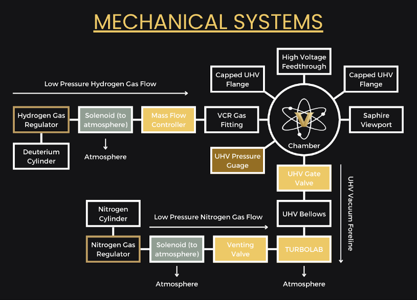 Figure 1: Schematic of Vacuum and Gas System
- Electrical Systems
The system starts with a control terminal, which has a keyed switch for security and an emergency SCRAM (shutdown) button. A warning light indicates the system’s operational status. Voltage control is achieved through an encoder that provides analog control over the voltage applied to the inner grid. This control adjusts the voltage supplied, with a voltage-to-current converter regulating the high voltage.
Multiple sensors are part of the system, powered by a small DC power supply, ensuring proper monitoring and feedback. A ballast resistor of 60 kOhms is placed between the high-voltage power supply and the fusor. This resistor helps stabilize the current flow and prevents rapid changes in voltage or dangerous power spikes, ensuring smooth operation.
The chamber itself is electrically grounded, as is the entire system, to maintain safety and prevent electrical buildup. The high-voltage power supply has a negative polarity, applying up to -50 kV to the inner grid. The operating current is up to 10 mA, and the maximum power output is capped at 500 watts, all delivered through the 50,000-volt feedthrough, insulated by beryllium oxide.
The concentric inner grid, where deuterons are accelerated for fusion, consists of made from 1 mm diameter tungsten wire. This grid is mounted on an alumina-insulated steel stalk, which provides mechanical support while electrically isolating the grid. The tungsten grid creates a strong negative bias in the center of the chamber, drawing positively charged ions toward it. The outer spherical chamber is connected to earth ground, creating the potential difference that drives the fusor’s operation.
Below is a schematic of our current electrical system:
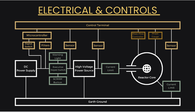 Figure 2: Schematic of High Voltage Electrical System
- Stainless Steel Spherical Chamber CAD Model
- Reactor Photos
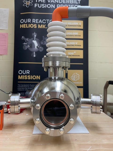
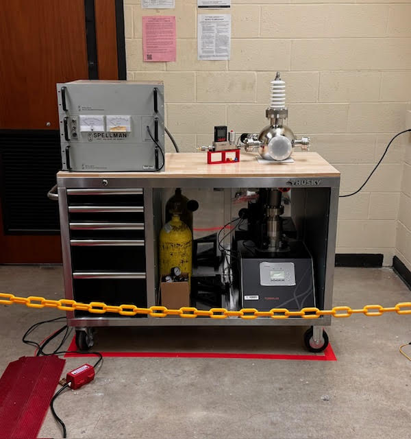 Figure 3: Front View
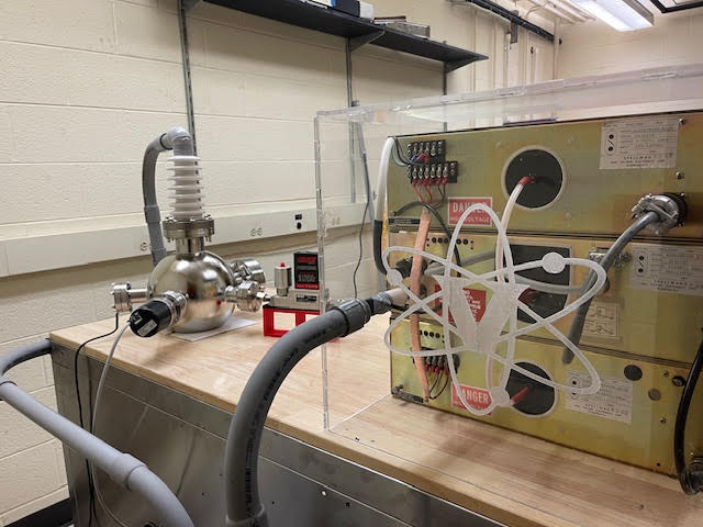 Figure 4: Back View